![]()
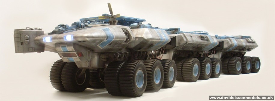
Replicating the Overlander from Gerry Anderson & Christopher Burr's Terrahawks
|
|||
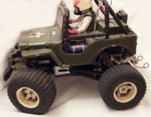
| I really liked this model and it became a big part of my Gerry Anderson collection, but unfortunately I had to give it up in 2002 during negotiations to acquire my all-time-favourite model - the original 44" Eagle 1 from 'Space: 1999'. | |||
 |
|||
 |
|||
 |
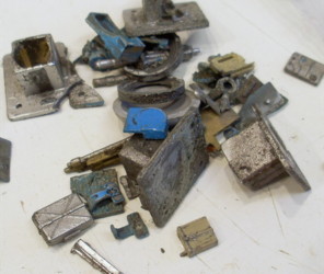
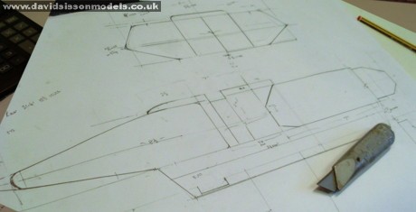
Having owned the original Overlander I never really thought about building a replica of it until a few years ago, when I saw the model again just before it went off to its new (and current) owner in Canada. I always considered such a project to be too problematic and also doubted that it could be done properly, with the main problems to overcome being the 36 large wheels that make up a big part of the vehicle, plus of course trying to draw an accurate blueprint. Then in early 2013 I came across my old collection of photographs taken when I restored the original studio model. These showed almost all the angles on the three bodies and, more importantly, provided some key measurements that would allow me to produce a good blueprint. As I was now intent on building a set of all the main Terrahawk vehicles this made the Overlander a probably future modelling project. I also then came across
a bag of old parts taken from the original model that due
to their poor state had been replaced during the
restoration process. These could now be cleaned up and
reused on a replica to give it a bit of originality! Nice
idea but there was still the problem of the wheels - then
I received an email from someone who happily told me that
Tamiya had recently re-released the old tyres and I could
actually buy them all. |
 |
 |
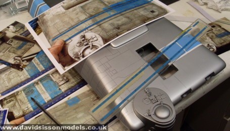
| Picture above left: some of the pieces remaining from the restoration of the original studio model. Pic above: starting to draw the blueprint. |
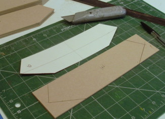
The first task was to draw the
blueprint, which is not a complete highly detailed plan
with every nut and bolt showing, but instead just a basic
outline showing the key details. Also only a front and
side view of the front body was required, the top view
not being required as those details could be worked out
on the build. Similarly no plan of the rear two bodies
was required as they were a more simple design that
followed the main details of the front body - only the
unique backend piece would need drawing. The chassis
would be added to the plan later. |
 |
 |
 |
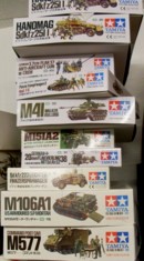
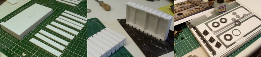
From the beginning I also began the rather tedious process of trying to identify ever model kit part used to detail the original build. Something that from the start I realised would be virtually impossible, but I was pleasantly surprised at just how many I managed to spot. Luckily I already had a head start having restored the badly damaged original model 20 years beforehand, so I knew some of the main kits that I would require and set about ordering them from ebay. Others would require visiting a model shop and looking through all the boxes at the various sprues. I drew a line at only looking through Tamiya military kits from World War 2, as that appeared to be the main source for Terrahawk models.... and I couldn't try everything, as shop owners really don't like you opening up all their stock on a whim! Luckily Hobbycraft leave their boxes open so I bought a lot from them. The original studio model was carved out of solid blocks of wood, something that I had no intention of doing. Instead I would make the shapes from flat material and sand off the edges. Plastics were of no use, as I would need to round off a number of areas quite excessively. So I decided to use 3mm MDF sheet as it was very easy to work with, but as this was a bit thin and would deform rather easily I had to use two sheets for each piece. The advantage to doing this is that two thin sheets glued together are supposedly stronger than a single thicker sheet. But also by cutting the second sheet slightly smaller, with 3mm removed from all the edges, I created rebated joints that are also far stronger than a standard butt joint. |
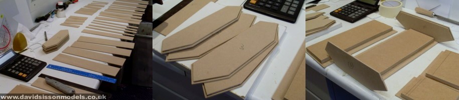 |
I started on the rear bodies as they were a more simple design. Beginning with the baseplate, adding the end pieces and filling everything in between. Originally I was just having the end pieces holding everything in place but worried about the sides loosing their shape, so I added a central bulkhead which stiffened up the structure nicely. I didn't try to cut every piece to fit perfectly but allowed some extra material to overlap in places just in case I needed to re-adjust things. These overlapping parts would be removed easily during the sanding stage. |
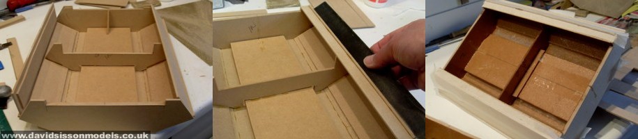 |
PVA glue was used to stick all the MDF parts together; this is a rather slow adhesive so I used pieces of tape to hold things in place whilst it all set. Also when gluing together all the two-layer parts I sandwiched them between two flat surfaces with a heavy weight on top for 24 hours, so they came out nicely flat. As a heavy chassis would later be attached to these lightweight bodies I had to beef them up by fixing 12mm thick pieces of MDF long the bottom of each section, giving me a secure base to screw into. Once this was all done I brushed a 2-part epoxy resin around the insides, together with some fibreglass cloth, to bind the structure together. Masking tape applied around the outside edges stopped any leakage during this process. |
| Photos below: Assembling the front section |
 |
| Cardboard templates were used to quickly work out the exact shape of the angled side parts |
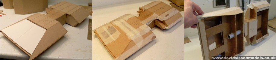 |
| A plastic tube was inserted along the centre of the model, through which I could later feed wiring for my headlights. |
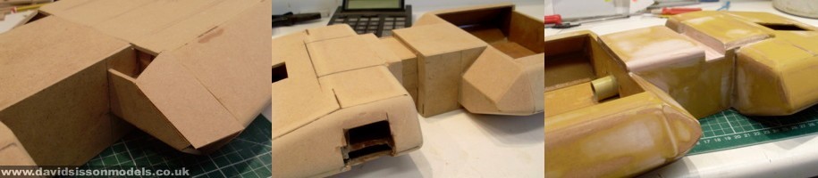 |
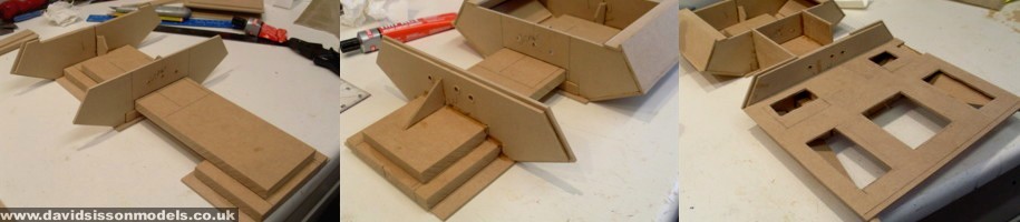
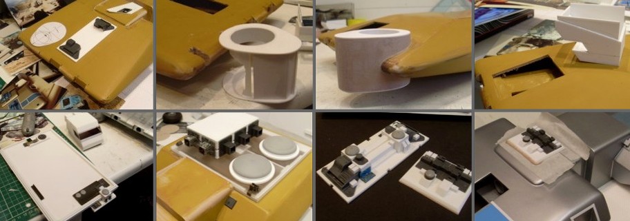
The front section was rather more
complicated but followed the same basic process. The big
problem here was that the forward wedge-shaped section
was almost entirely enclosed which meant adding the resin
to the inside would not be an easy task. Also I had been
thinking of adding some lights, especially the two
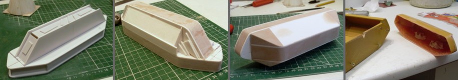
headlights and maybe something in the drivers cabin. When all the glue and resin was set I began sanding down the structures, which is a fairly easy process with MDF. Care must be taken as MDF is supposed to be hazardous to your health. I always use a twin-filter facemask and have an extractor fan next to the piece I'm working on. Every few minutes I clear away the build up of dust and wipe down the work surfaces with a damp cloth to minimise the chances of the particles getting airborne. When I was happy with the shape of my three hull sections I coated them with a 2-part epoxy resin called SP-106, which I buy from a supplier on ebay. This takes about a day to set properly, which means that I usually give it longer and keep the parts in a warm place to help them cure. Afterwards I sand them down using wet & dry paper (on a block) to get a smooth flat finish, without trying to get things too wet in the process. Of course things never actually come out 'perfectly' at this stage, so bits of filler and several coatings of spray filler followed by yet more sanding are required. |
 |
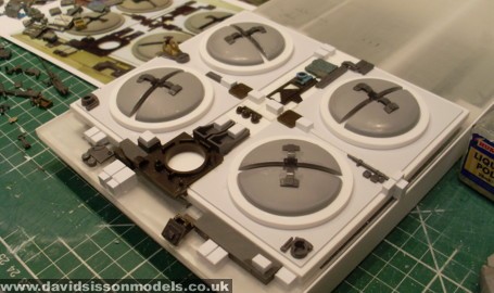
Although the front and rear parts of the Overlander are unique shapes the other end-sections are all of a similar design, so it made sense at this point to make one master and cast up the four repeated pieces. Plasticard was used to form the basic structure and then car filler was applied in stages to fill all the gaps and block out the overall shape. Pics Above: small pieces of Plasticard were cut up and glued into the holes during the process. This minimises the amount of filler required and also gives it something to securely bind on to. You don't want to spend hours sanding something to perfect shape only for sections of filler to fall away after you have finished! When completed I made four
plaster-of-Paris moulds of this master pattern and then
cast up the end-sections in fibreglass. |
 |
Pic left: Further coatings of spray filler and more sanding and the model was starting to look the part. |
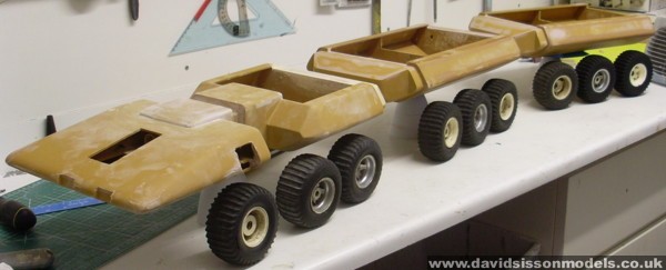
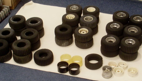
Above: Here I balanced the parts on
some boxes to judge the height and placed the wheels next
to it to get an idea of what it was all going to look
like. At this stage I was still building a 36-wheeled
vehicle with only around ten wheels to my name! As
mentioned before the wheels/tyres were a bit of a
nightmare. Every time I start a new project the first
thing that I think about is any piece on the model that I
can't actually make, or that I can make but really don't
want too! Clearly 36 wheels with big rubber tyres came
into this category. My limited knowledge of these items
were that they came from a Tamiya radio-controlled toy
that was obviously around in the 1980s. The design is
rather unique and is apparently called a Paddle tread,
and that they have the word 'SAND TIRES UNLIMITED' marked
on the sidewalls. |
 |
This came as something of a shock to me after I had bought some of these new tyres and placed them on top of my blueprint. For a few minutes I thought my eyes were playing tricks on me, then I thought I had made a catastrophic mistake in my calculations and had drawn everything too big. |
 |
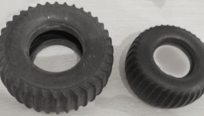
The Internet came to my rescue
after I did a search and found someone asking the same
question about tyres on a specialist forum. The picture
above left demonstrated the answer. The tyre re-released
is on the right and comes from a popular 'Sand Scorcher'
VW beach buggy, while the bigger one on the left was used
on the 'Wild Willy' (above right) and 'Blazing Blazer'
cars. In the end it took me around 15 months to get all the tyres I needed off ebay. Luckily some people just sold the tyres/wheels as spares, and as they are often not in prime condition I could get them reasonably cheaply. Also after some people won the toys on ebay I would email them to see if they wanted to sell their old tyres and managed to source a few that way. These rubber tyres were not really made to last forever and the biggest problem is that they start to crack up, especially on the sidewalls. This is something that I had encountered before when restoring the original model in the 1990s, but as the Overlander is just going to be a display prop it doesn't need pristine tyres, and I could even afford to get away with having holes in them if I had too. One other problem was that the tyres were coming to me on two different styles of wheel, made from either metal or plastic. Also some had foam inserts and some did not, and when I just bought tyres on their own I obviously didn't have wheels to put them on, or foam inserts, or a large plastic tube that fits inside to support the rubber tyre. Clearly I had more problems to overcome on the wheel front, but for the moment I just stacked everything up on a shelf while I carried on building the rest of the model. |
 |
| Some kit parts were actually cut up and repositioned on the original build, making identification more difficult and time consuming. |
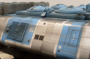
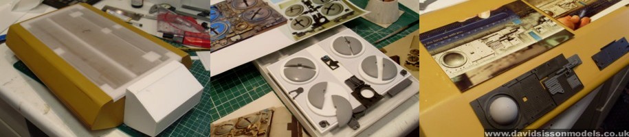
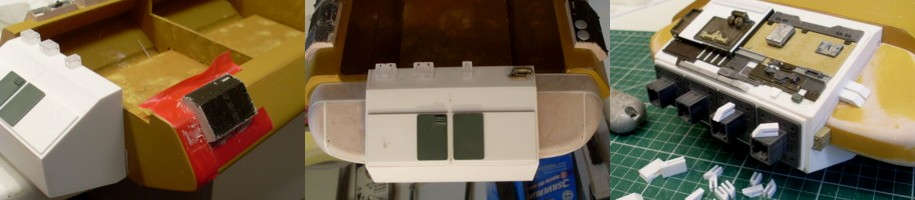
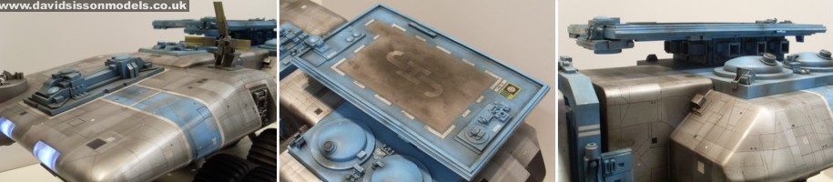
All three wooden bodies have open tops that are filled in with plastic covers that I made from Perspex sheeting. This very smooth sheet is rubbed over with wet and dry paper to give the surface a matt finish, making it easier for the glues and paint to adhere. More strips of plastic and tube are glued to the underneath to make the sheet ridged and stop it bending. Then the upper surface is detailed with more sheet plastic and assorted model kit pieces. At the same time more model kit parts were glued to the wooden hulls. I scanned my vintage photographs into the computer and printed them out to full-size to help me to identify all the parts. Luckily I managed to identify and source every kit piece on the hulls, except for one small section on the front body that had been missing when I got the original model. Even watching the DVDs didn't help, so I had to invent that detail but used some of the remaining original parts I had. |
 |
The rear section has three angled
kit parts mounted on the sides, which come from the
Tamiya M577 Command Post Car. The parts were held in the
correct position using small blocks of plastic, then
filler applied around the gaps to create the sides. This
was all smoothed off with a knife and files while thick
insulation tapes protected the surrounding surface. The
one piece on the rear left is an original part which I
manage to clean up to an acceptable standard and reuse. The two round rear edges were formed in Plasticard and filler, following the technique mentioned previously. The only difference here being that they are actually used on the model and not moulded. Once I had sanded them to shape I had to cut away the exposed thin white plastic edges and fill in the resulting gaps to get a consistent surface. If I had not done this there was the possibility that the two materials could have produced imperfections, or even cracks, in the finished paintwork in later years - as no two materials will react exactly the same way to temperature changes. |
 |
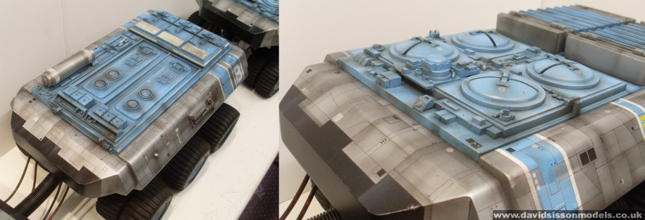
Two large 'ribbed' sections sit on
top of the rear body. On the original model these were
fabricated from differing sizes of thick Perspex, all
sandwiched together. I took the easier option of making
box-sections and adding strips of thick Plasticard, then
sanding everything down to hide all the join lines. |
 |
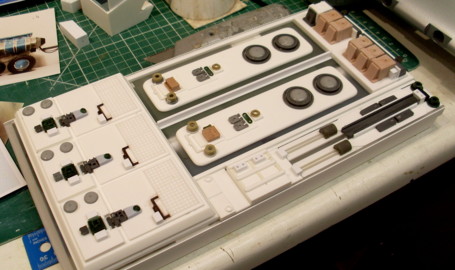 |
| Rear section almost finished. The domes are EMA
parts cut in two, the hatch covers on top being chair
backs from a German anti-aircraft gun. Above right: The top of the middle body finished. |
|
Detailing the three Perspex
top-sections took weeks of work, firstly having to
fabricate the various surface layers in Plasticard before
adding all the kit-part detailing. The best result was on
the rear section where I identified just about every
piece, the front section was almost as good but then
again it was much smaller and didn't have that much
detailing. |
 |
Above: Further detail work on the front body. Again mostly EMA and model kit parts together with an assortment of plastic sheeting and square tubes. |
The three hulls were painted with
'Halford' brand motorcar spray cans, Ford Olympic Blue
and Mini Pure Silver. Once this had properly set I could
draw the hundreds of panel lines onto the model's
surface, a rather long process but not quite as hard as I
had first feared. I started by scanning my old photos
into the computer and printed up larger copies to make it
easier to see what I was doing. |
 |
 |
| Above: starting to add the panel lines (I still have the same ruler!) and I finally locate 36 usable tyres |
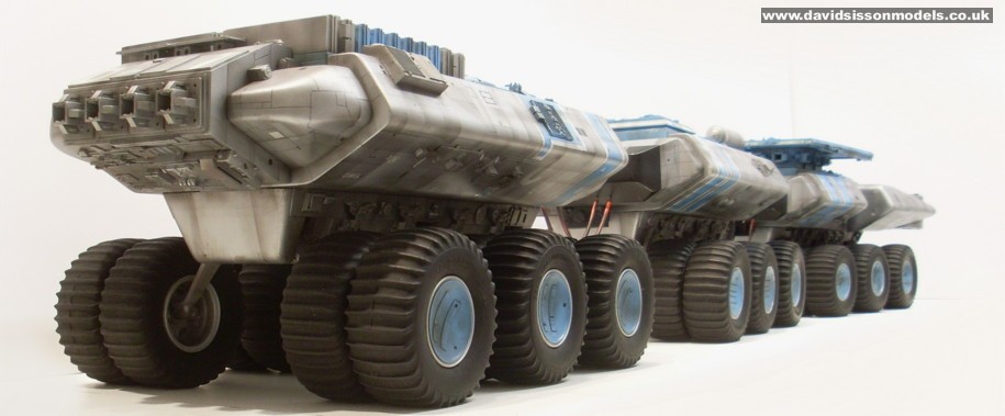
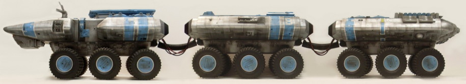
The model was now close to being finished with one major problem to tackle - the chassis. This consisted of 36 large wheels, which needed to be paired off into 18 units, and then attached to 9 brass axle supports, which in total would use around 500 parts! The first job was to dismantle all the
old wheels that I had bought and give them a good clean,
then figure out what was missing. After this I had to pair them off and decide where they were to be positioned on the model, which involved a fair amount of thought as the tyres were in such a variety of conditions. First of all I separated them into three sets of twelve, one for each body. The front body would have the best tyres as it is the most interesting shape and the one most people will spend their time looking at. The rear section would have the half-decent tyres as again people would tend to look and photograph the model from either end. This would then leave the centre body to have the crappy tyres! |
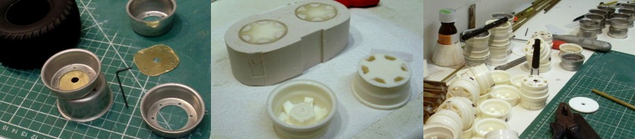 |
Although they were all the 'same' tyre design they had aged differently over the years, some getting slightly fatter/shorter or taller/thinner. So the next job was to pair off each of the twelve tyres into similar looking types, so that they would look right when positioned closely together. Also I had to take onto account the tread pattern and realise which way round the tyres would fit on the axles and be finally viewed. As each tyre had its good and bad sides I needed to make sure that only the good sides ended up on the outer edges where they would be seen...... so it was a major puzzle. The next puzzle was the wheels
themselves, just to make things even more complicated I
had three different types to contend with - one metal
version and two slightly different plastic ones (The
original model had metal wheels on the first two bodies
and plastic on the rear). All of the wheels were paired off and glued together, with a brass tube running down the centre to take the axle. The plastic wheels could just be drilled to take the tube but the metal ones required brass plates to be sandwiched between the wheel halves and then soldered to the tubes. The rubber tyres were mounted on the wheels during this assembly process together with an internal plastic tube (again duplicates had to be cast) that supports the internal sidewall structure, together with a foam insert to fill out the tyre. |
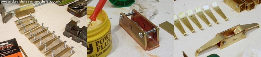 |
To support this big model I needed a strong chassis so all the parts were cut from heavy 1/8th inch Brass sheet. My biggest concern was making sure that everything was going to end up in the right place at the end, with the wheels being at the required height, pointing in the right direction, and extending away from the body to the correct distance. To this end I drew, and redrew, the blueprint numerous times until I was finally satisfied that I knew what I was doing - then I built a wooden jig over this plan to hold all the parts as they were soldered into place. |
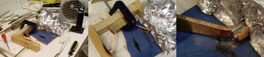 |
The axles were hollow so that a long metal rod could be run through each pair during the soldering process to ensure they remained in-line with each other. Obviously wood doesn't tend to like a blowtorch so I used pieces of baking foil to try and prevent everything from catching fire! |
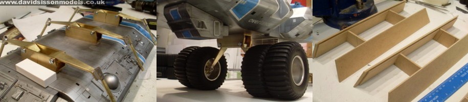 |
The finished brass axles were
cleaned up with wet & dry paper and screwed to the
wooden bodies. |
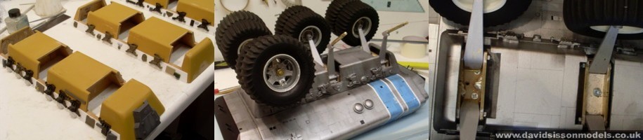 |
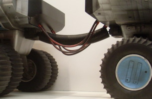
The parts were given a light sanding and coated in spray filler. Any holes that were found were then filled and sanded smooth. Then they were detailed with plastic kit parts which mostly come from the 1/35th scale Tamiya Sherman tank. The pivoting arms that support the axles were brush painted in matt aluminium, as were the inner wheel hubs. Rubber pencil erasers were trimmed to size and screwed into position between the support arms - these hold the chassis arms in place but allow a certain amount of movement to occur. With all the wheels now attached I could assess the model and make a few small alterations to the chassis. The axles were slightly longer that required and this allowed me to finely adjust the positions of the wheels using a selection of small washers, before locking everything into place. Finally I vac-formed all the hubcaps from 30-thou plasticard and glued them into place. With this major model build almost
finished I actually got stuck on the very final detail -
the two big hoses that connect all three bodies together! |
 |
This hose was pretty much perfect,
but it didn't droop in the middle like the parts in the
television show did. So I filled the tubes with car
filler and bent them to shape whilst the filler set. |
|
||
 |
||
| Unfortunately
the Overlander is a well-weathered model and after
applying plenty of powder paint I realised that I wasn't
getting the results that I needed... so the airbrush came
to the rescue. This time however I opted for using
water-based acrylic modelling paints, black, grey, and
brown, which went on very well. So after two months
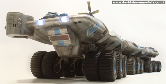
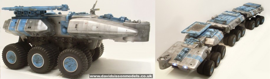
retirement the airbrush is back. The Overlander is one of the biggest models that I have built, at a length of around 63 inches (160cm) |
||
 |
 |
Replicating the Overlander; Text and photographs copyright David Sisson 2016