![]()
Scratchbuilding Thunderbird 3 from Gerry Anderson's classic 60s TV show
 |
||
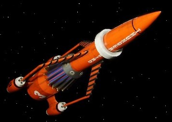
I seemed to have spent most of my early life watching 'Thunderbirds' on the television, reading about it in the classic 'TV21' comic, or playing with the toys. My clear favourite was Thunderbird 2 with TB4 and TB1 somewhere after that. Thunderbird 5 was easily the worst and so that left Thunderbird 3 as.........I'm not really sure? Considering my long-time interest in space travel you would have thought that I would like TB3 but it has never really grabbed my attention and I'm not sure why this is - because it is an original and striking design. But I guess at the end of the day the vehicle was never in the midst of the action, firing lasers, chasing other ships, or crashing like an Eagle would do each week - it just sort of went straight up, and down, in the way that rockets do! |
||
|
||
 |
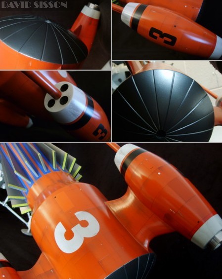
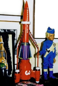
After the problems of building the very shapely Thunderbirds Two and Four it was a relief to tackle a far more basic and straightforward model. Thunderbird Three, like TB1, is a simple tubular craft that only requires a couple of decent reference photographs to construct a very accurate replica. With the continuing popularity of Thunderbirds photographs are easily available and with the simple and repetitive design it was only necessary to draw an outline of half the model. The craft was represented, on screen, by three different scaled models and their general overall contours are reasonably similar to each other with just a few differences in certain areas. However due to wear and tear and the upgrade and refurbishment for the feature films they all have differing paint schemes and minor detail changes from photo to photo, with the medium sized model having at least four different finish's. Normally I like to pick a favourite studio model and build an exact copy but with this craft I decided to make a standard shaped version combining what I considered to be the best detailing from the originals. Although my collection of T'birds isn't built to the same scale I decided that with the others being between 20 to 40 inch's this one would need to be towards the bigger end and picked a length of 34 inches, which makes it big but still reasonably easy to handle. |
|
The Build by David Sisson
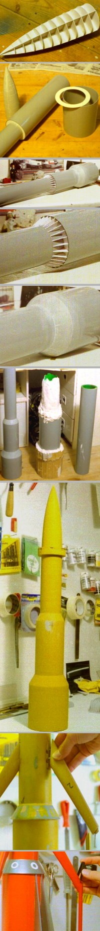
The nosecone was one of the first bits to be tackled, and as I didn't have a lathe to turn it, I had to resort to making the shape in Plasticard. Here the tapering outline of the nosecone was made from two outline pieces, which were cut up and glued together at a 90-degree angle to each other. Then a series of discs were cut into quarter-sections and glued into position to block out the general shape. The rocket engines were made using the same technique but this time only half the shape was formed. Once this was done more bits of plastic were used to fill in the interior space of the gaps and then polyester automotive filler was applied over this to completely fill out the overall shape. When I was happy with these master patterns I could use them to produce a set of plaster moulds. The nosecone could just be done in one moulding with the final part being cast up in fibreglass. Six copies were needed
for the engines with these parts being cast up in a
mixture of resin and P38 car filler. These halves were
sanded flat, paired off and glued together with more
filler to seal any gaps. To construct the
fuselage I simply had to order three sizes of plastic
tube from EMA Supplies. The two wider tubes were cut to
the required sizes and assembled on the thinner central
tube using 2mm Plasticard disc's with holes in the centre
(like giant washers). The reducing areas were again made
by forming the shape using plastic and car filler. Care
had to be taken not to sand down the surrounding plastic
pipe during the process. Moulding the long thin
hull in two halves can lead to problems when you come to
join them together, so I decided to try and mould and
cast the big main hull in one go. Here I applied plaster
of Paris to the master and used larger pieces of pipe and
cardboard to hold the wet plaster in place around the
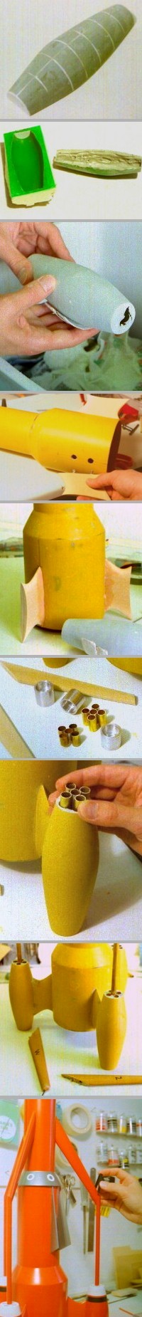
tall construction. Casting the model using this one-piece moulding was problematic as it was hard to get a consistent thickness of fibreglass throughout - or more importantly getting the material into the centre of the narrow plaster mould. I had to resort to swilling the resin from one end to the other and pushing the fibreglass matting into position with long rods. This was one very messy casting process but it did work out rather well in the end. (although there were a few holes in the middle of the final cast that needed filling) The nosecone was now
superglued to the main hull and the docking ring added to
cover and strengthen the joint. The whole model is coated
in layers of spray filler and rubbed down with wet &
dry paper for a smooth finish. The three engine supports
were cut from thick MDF sheeting. A centre guideline was
drawn around the edges and then the sides were sanded to
the line to create the aerofoil shape. These parts were
coating in resin and sanded further to achieve a smooth
tougher surface finish, then they were glued to the main
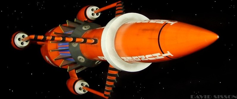
hull. When it came to the
engines I decided to copy the big studio model and have
the four retro-rocket tubes instead of just the one large
inlet. To do this I drilled out the end and fitted a unit
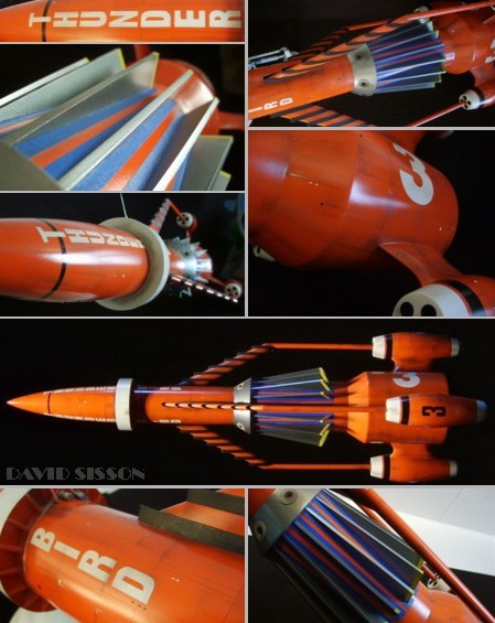
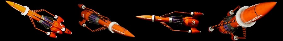
soldered from five brass tubes into place. The filler in the central tube was knocked out completely as this is where the arm tubes anchor in place. The three arm fins were
carved from wood and coated in resin, then sanded smooth.
Metal pins were inserted into both ends. One of the
trickiest parts of the construction was getting the three
fragile looking arms straight and equally spaced. The central cooling fins were cut from Plasticard and painted before being fixed in position. Again a tricky process to keep them straight and equally spaced on the hull; running masking tape around the hull with pen marking the positions helped. |
|
|
||
|
 |