![]()
Scratchbuilding Eagles from Gerry Anderson's Space:1999
|
|||
|
|||
|
|||
|
|
||
The
Builds ......By David Sisson The biggest problems
with scratchbuilding replica models is obtaining
information and then trying to recreate something you may
only have seen in photographs or on the TV. Luckily there
was a decent blueprint published in the eighties, in the
Gerry Anderson fanzine S.I.G. 10 drawn by Phil Rae. Even
better the original studio model has survived since the
cancellation of the series and has been available to
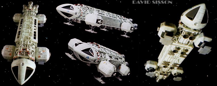
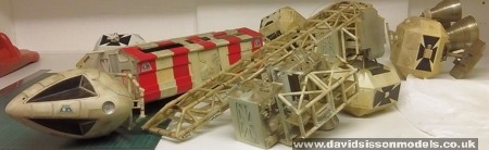
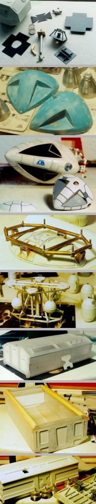
view. With this project there are two problem areas, the nosecone and the aluminium engines. In both cases you can make them yourself or (more normally) get someone else to do it for you. You can start on any part of the model first, but as the framework holds everything together then it is really the best place to begin. The first job is to get all the brass pipe needed for the project, on a 44" model that comes out at around 100 feet. Most of this is 1/4-inch diameter with some 3/16" and a little bit of 5/16". On a 22" Eagle I just buy the stuff from model shops (K&S brand) but for the larger model I had to find a stockist in the yellow pages under Non-Ferrous Metal Supplies. Most of the brass is hollow but I use solid rod for the connecting pieces - as I find that the solder has an annoying habit of wanting to disappear up inside the tubes. Picture below; Here a 44" eagle is split into its main components as per the original design. This helps with such a big heavy model but obviously it isn't necessary to have it like this on every Eagle, especially when the tail section keeps working loose - here I ended up gluing it into place. |
|
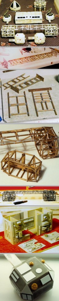
The first time I
built an Eagle I did it the hard way - cutting all the
pieces to the correct length and then trying to solder it
all together - WRONG! The two cages were slightly more difficult, here I assembled several areas before placing them in the supports and adding all the connecting pieces. Each cage section is actually two pieces - some people build them one piece at a time, I find it easier to build the two sections and then split them later - just leaving enough of a gap to get a saw blade between the pipes. All my soldering was
done using a mixture of Carrs 188 solid solder and solder
paint (from a model railway stockist) - and a mini gas
blowtorch. I assemble the parts using the paint then when
its all in the correct position I will use more solder to
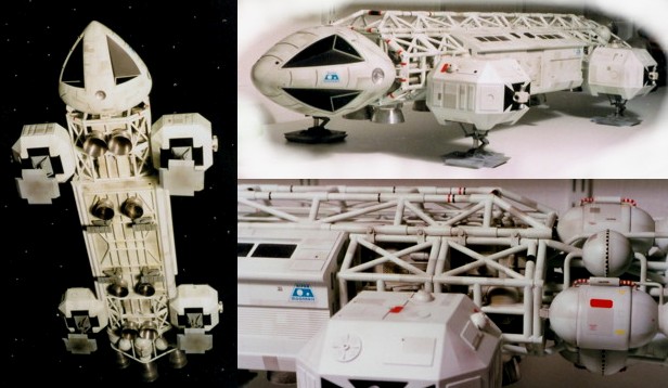
strengthen the joints and fill any small gaps. On the original big model the spine is just attached to the cages using 16 small bolts, on all my models I chose to solder the sections together as well for added strength. The corridor sections are fabricated from 2mm Plasticard and detailed with assorted kit parts. My normal attitude to replica building is constant accuracy at all times - but when it comes to these areas my attitude changes to lets do something better! This is partly due to the various studio models having different details on them (had they all been the same I would copy it) but really its due to the original detailing being so poor - it wasn't meant to be seen up close. The shoulder pods were next, in this photos (44") you can see the basic form being made in 4mm Perspex. I started with two outline shapes spaced apart to form the middle then glued the top panel in place on Plasticard supports. Then the angled panels were cut out and glued into position - that's after all their edges had been filed and sanded to shape, which was a long process. These pods were made as hollow shells then filled with resin to strengthen them up. A Plasticard box inserted into the pod during the process held back the resin and created a central cavity to give space for the later addition of the landing leg support and to keep the weight down. The outside was detailed
with pieces of Plasticard and kit parts - although on
this model many of them were castings as the originals
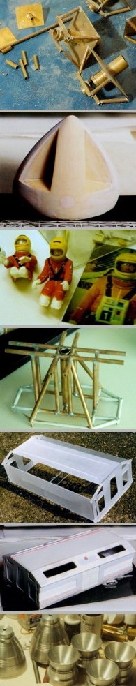
were in short supply. The supports for the landing legs are formed in brass. On the 44" models every time I pick them up, or try to take pictures, the legs are at slightly different lengths with the footpads pointing in slightly different directions, pivoting at different angles - or the back supports break. On the 22" model I just fixed them in position - problem sorted. Picture above right - All the components for one 44" shoulder pod. The footpad was cut from a piece of thick Perspex matching the studio model as it is today - but during the first series the pads were apparently thinner and dirty white in colour. The small faint panels around the edges were created using paper labels. I use to think the black cross behind the attitude thrusters was just done in paint, but it is a raised detail cut from thin Plasticard. On my first models I
carved the nosecone from balsa wood, on my 44" model
some castings taken allegedly from an original moulding
turned up and were very good. My 22 " model was
originally an AB Models kit, however due to many parts
being either badly formed or just plain wrong I ended up
discarding around 75-80% of the kit and scratchbuilding
most of it. The nosecone casting from the kit proved
useful in the construction of a new master as it was
slightly undersized and could be built upon. The raised
panel detail was removed and thin Plasticard was added to
the window areas to form the correct proportions, then
the rest was skimmed over with filler and sanded down to
a better shape. Three plaster moulds were taken and the
final parts produced in a thin fibreglass casting. The
front two were glued together and more resin added to the
inside to create a strong join. Then the raised panel
areas were drawn onto the surface and pieces of
Plasticard heat-formed around the required parts, cut out
and superglued down. I've always tried to put a detailed cockpit interior into every model, but at the end of the day I have to admit that it doesn't really fit properly and after you have done it all you cannot see too much unless you have a light fitted, as I did with the 22" model. On the 44" model I modified two racing driver figures but more recently I just use the Revill Gemini 1/24 or 1/48 scale astronaut figures. The windows are the last bits to be added in an attempt to minimise possible scratching. The hull above the windows has to be cut back very slightly, equivalent to the thickness of the clear plastic, to allow them to fit. This normally creates a visible join line that has to be covered over - I usually don't mess around trying to fill this thin line but actually make it bigger by cutting a V-shaped groove, half the V from the plastic and half from the hull - then filling this bigger strip and sanding smooth. Unfortunately I did scratch one of the windows on my 22" model and fixed it by rubbing over with very fine wet&dry paper and then spraying with clear lacquer. |
|
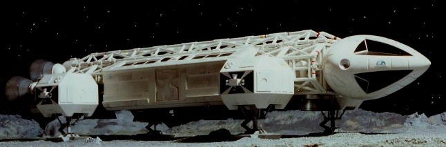
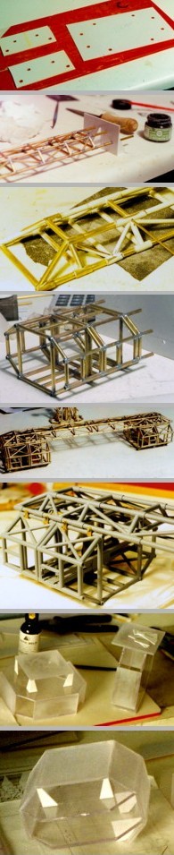
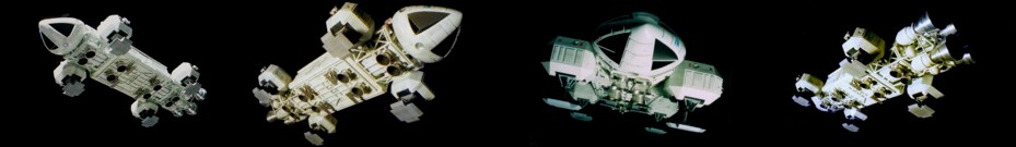
The engine assembly
is just a brass frame with a cluster of fuel/combustion
tanks made from EMA plastic domes and plastic tube. Here
the plastic tube was actually from a pet shop. The design
of this area changed for the 2nd season of the show when
extra pipe work was added to supply gas to the main
engines. As I love the look of complicated pipe work I
copied this design although many people prefer the
uncluttered 1st season look. At the moment I have only made the standard passenger pod although two of the pictures here are of a Lab pod under construction. As the pods are just simple box's they are the easiest bits to make and are constructed from plastic sheets. Here I just traced around the end of one of the original pods and cut two copies from Perspex. The recessed panels and doorways are drilled out then blanked off and detailed with Plasticard. The sidewalls consist of two layers with the design cut out of the surface layer. These are glued into position along with the roof then finally the angled window areas- here a thin bit of Plasticard is inserted into the centre recess as this part isn't as deep as the surrounding window areas. The angular parts on the bottom edges of the pod were formed using wood stripes together with some car filler. The window areas were made from clear Perspex, but you paint them black on the inside and that gives them a deep pure black gloss finish from the outside. The 12 windows were created by applying masking tapes during the painting stage, so the thin window surrounds are simply a layer of paint and not a thick solid item as such. The bottom of the pod is a separate piece that screws into position. The pipe work here was thin-walled brass from model shops (to keep the weight down), mostly glued together as it's just for decoration. The pods feet were fabricated from brass as well - although the footpad detailing is plastic. The main supports extend through holes in the bottom of the pod and are cemented in place with car filler to make sure they don't snap off whilst being handled. The models are painted with motor car spray paints, some in cellulose - nowdays acrylic. Weathering is airbrushed enamel paints with graphite pencil just applied with a finger. Coloured bands are paint or tapes. |