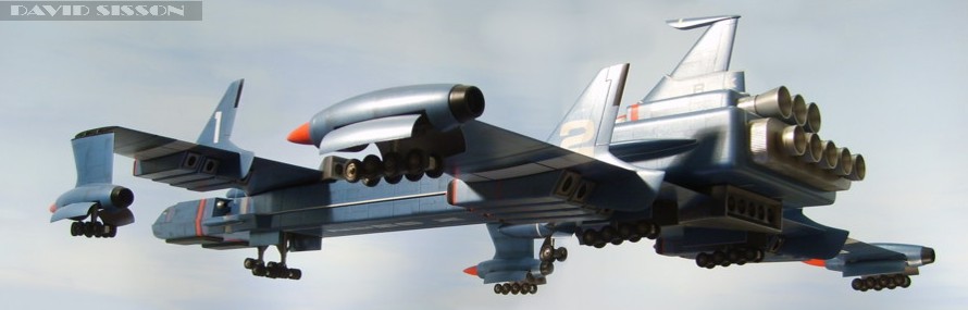
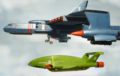
LIFTING BODIES
One of the
reasons for the delay in completing this model
was that I was unsure of how to construct the
large wings; I was also worried that after
building them they would both end up drooping!
My basic technical knowledge told me that several
layers of materials glued together, in a
composite, are stronger than one thick material
as they act against each other. So I decided to
build up the shape of each wing using layers of
different materials starting with the basic
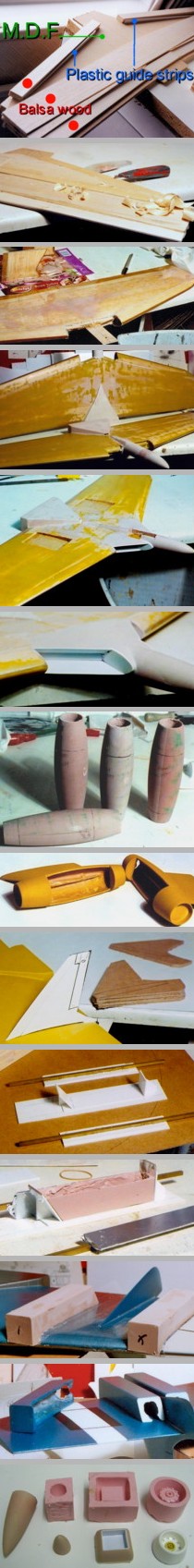
outline cut from thin MDF.
This MDF sheet
became the horizontal centre of the wing with
sheets of Balsa added above and below to create
the aerofoil shape. As the wing thickness also
reduces towards the wing tip I glued plastic
tapering strips into place behind the leading
edge in order to act as guide markers for sanding
down the Balsa to the desired angles. Weights
were placed on the sheets of wood to keep them
compressed while the glue set, after which I
could then begin shaping the wings by firstly
trimming off the obvious surplus wood with a
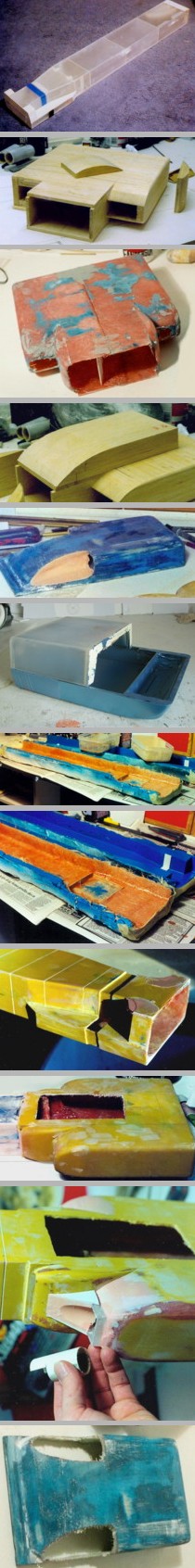
knife. The pictures here show the front wing
which was easier to work on as both wingtips were
made separately. Later in the process I removed
the rear protruding engine area and the two front
inlets..
The next stage
was to spend a great deal of time sanding the
wings down to the correct shape - and then to
take them down even further, as the wood needed
to be given a fibreglass coating which would add
to the overall thickness.
When they were ready I gave the wings a coat of
SP113 laminating resin, this is a two-part epoxy
resin (used by radio controlled model aircraft
and boat builders) that depending on the mixture
and temperature takes up to a day or more to set
properly. This initial coating sinks into the
wood and when set leaves a rough surface finish
that needs cutting back with wet & dry
abrasive paper. I then checked over the wing for
any major imperfections that needed correcting
with car filler before applying another coating
of the resin. This next application also included
fibreglass tissue, to give the wings extra
strength, and it had to be applied very carefully
to prevent any lumps appearing. Again it was all
left for several days to thoroughly set before
being sanded down and a final topcoat of resin to
finish it all off. Then the wings were then
treated with several coats of spray filler and
sanding began again with any uneven areas and
holes being fixed with car filler..
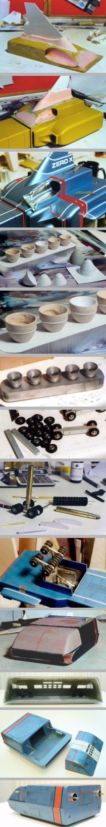
Picture right;
shows the rear wing, with the areas for the
undercarriage being cut out. There isn't really
enough room in the wing for the wheels to fit but
I preferred to cut a semi-recess than just fix
the undercarriage to the wing surface (which is
often seen on models that appeared in Gerry
Anderson TV shows).
A master pattern
for the bullet shaped front end was sculpted,
moulded in plaster and then two copies cast up in
a resin/car filler mix. These were then secured
to the MDF core of each wing, with the
surrounding air-intake areas formed in plastic
sheeting which was all blended into the wing with
more filler..The rear triangular engine sections were
made in a mixture of plastic and filler.
For the outer
wing fairings I made a master pattern of only
half the shape then cast up eight copies and
paired them off.
See the Thunderbird
3 build for
details on making this type of shape.
The areas for
the undercarriage hatch covers were pencilled
into position and drilled out. Slots were also
drilled out to allow the fairings to be embedded
onto the wingtips, superglue held them in
position whilst car filler was smeared around the
parts to securely lock everything together..
The vertical
fins on the wings were formed from MDF. A centre
line was drawn around the edges of each fin and
then they were sanded down to an aerofoil shape,
coated in resin and sanded smooth. Cardboard
versions were used to test the final shape and
position. The fins are one of the items that are
very different on the two studio models.
Slots were cut into both the fins and wings
allowing them the lock into each other. Then the
parts were glued and filler used to blend them
together..
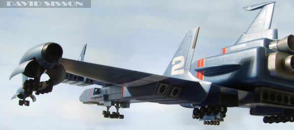
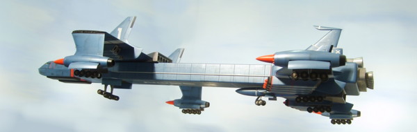
The next problem
was building 16 engines!
Repetitive jobs are something that I hate doing,
as I'm usually very bored by the time I've made
the fifth identical part! Although the engines
look like square boxy shapes they do have very
round edges so making them from plastic sheeting
would not only require a lot of pieces but then a
lot of hard sanding.
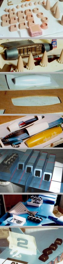
The answer, again, was to cast the parts in a car
filler/resin mixture using some sort of mould.
For speed I
decided against making a rubber mould and opted
for a solid plastic one that could be taken apart
to release the castings. Here a centre core forms
the main shape with the sides, strengthened with
metal rods, simply held in place with elastic
bands.
As the mixture dissolves styrene plastic I had to
cover the parts in adhesive metal foil that I
waxed to help prevent the filler from adhering.
The aerofoil
shape of the wing was cut from the sides of each
engine using two templates as a rough quick
guide. Then each engine was carefully adjusted to
its correct position and numbered so I didn't mix
them up. To create a perfect join a small amount
of filler was applied to each edge and then the
engine bodies were pushed into place against the
wings surface.
The surplus filler that squeezed out of the sides
was trimmed off as it began to set, whilst the
wings paint surface was protected during the
process by temporarily covering it with clear
adhesive tape. Note - The tape is first applied to
either my skin or trousers to kill off some of
its adhesive strength and stop it from lifting
the paint when it is removed. .
Because of the
tape all 16 engine bodies could then be easily
prised off, sanded smooth, painted, then
reattached using clear 2-part epoxy glue. More
detailed multiple parts had to be produced using
rubber moulds. These were all painted prior to
being fixed in position.
There are no
reference photos of the inside of the wheel
housings so I just had to invent something that
looked good. The hatch covers were vac-formed in
0.75mm plastic sheet over the master pattern.
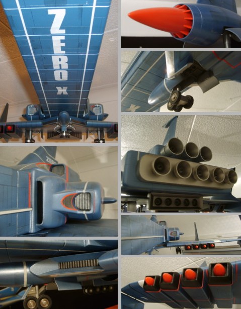
The large inlet cones were temporarily glued into
position whilst the series of small plastic vanes
were applied around the base, each one having to
be trimmed to perfectly match the gap, then the
finished part could be snapped free and painted
before being permanently attached.
The large
numbers were spray painted on using masking tape
outlines. Letraset numbers were enlarged to the
right size and used as a guide to cut out the
shape from the masking tape. These numbers were
placed on the model and moved about until they
were in the right position, then the surrounding
tape was placed back over it and the number
removed. The edges of the tape were carefully
pressed down, to stop any paint from bleeding
under it, and then the paint applied in a series
of light coats, again to prevent bleed through
and get a sharp edge..
More sets of
wheels were now assembled. Luckily the front wing
only has two sets but the rear wing features
five, which includes a small steering unit. The
two main centre sets were soldered to Brass
plates that were glued into the wing recesses.
|